Hardware Setup
Installing the board:
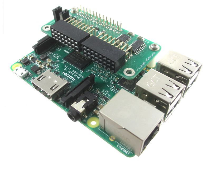
- plug the shield onto the Raspberry pi, taking care to line up the pins to the outside corner of the board.
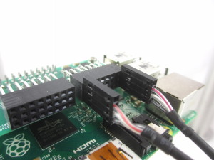
| The add-on board connected to a Raspberry Pi 3 B
|
|
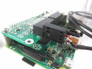
| The add-on board connected to a Pi Zero*
|
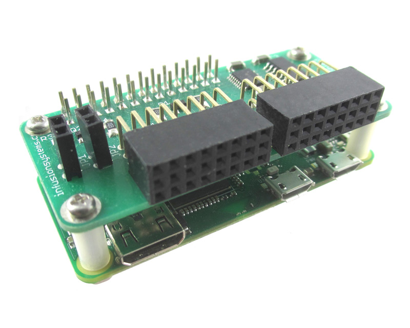
Note: for the Pi Zero, you will need to solder some male headers to the board.
The board supports up to 4 digital sensors, and 8 analog sensors:
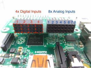
Analog sensors
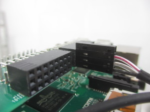
- plug in your analog sensor(s) onto the headers on the right side of the board. Make sure the orientation is correct (red wire of sensor should be at the top)
| This photo shows a single analog sensor plugged into the first port
|
This photo shows two sensors, one in the first and last analog ports
|
And thats it! Proceed to the basic C examples page, or back to the documentation index!
Digital Sensors
For digital (I2C) sensors, there are 4 ports available.
This photo shows a digital I2C sensor plugged into the first port |
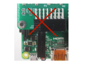
Take care to align the digital sensor. The image below shows an incorrect configuration |